Driving from the Drumcliff side into Ennis town centre, you cross the River Fergus floodplain—soft alluvium and buried organic silts that tell one story. Move south toward the Ballybeg area and you hit the limestone bedrock of the Clare uplands almost at surface. That sharp contrast, within a few kilometres, is why a standard borehole log in this town can miss what a seismic refraction profile catches in a single spread. We use seismic tomography to map the transition from compressible drift to competent rock. For the 27,000+ people living across the Ennis municipal area, founded on karstified Carboniferous limestone, knowing where the pinnacles, clay-filled grykes, and open voids sit is engineering common sense. The refraction method gives us a velocity model of the top 30 to 40 metres, which we cross-check with any available CPT logs to tie the geophysical boundaries to actual soil behaviour.
A velocity cross-section along the Fergus floodplain often reveals more about the rockhead geometry than five scattered boreholes.
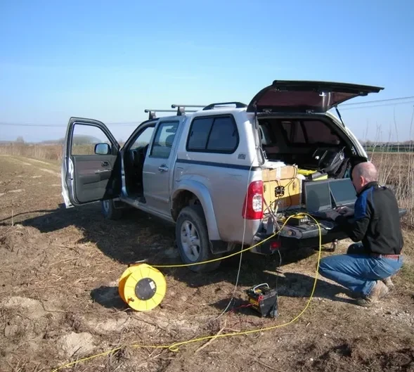
Methodology applied in Ennis
Critical ground factors in Ennis
A five-storey apartment scheme near the Quin Road bypass hit an unexpected soft zone during piling—three piles refused on rock, the fourth kept sinking through 11 metres of clay-filled dissolution pipe. We re-ran the site with a tomographic refraction line and the velocity gradient told the story instantly: a vertical chimney of 800 m/s material surrounded by 3,200 m/s competent limestone. The developer had to redesign the northern half of the foundation layout with a transfer slab. Without the tomography, they would have driven piles blind. Ennis sits on the Burren's southern geological fringe; karst is the norm, not the exception. Over-excavating a void and filling it with lean-mix concrete costs far less than fixing differential settlement after the blockwork goes up. The seismic data also feeds into any deep excavation design, where knowing the stiffness contrast between the drift and the rock governs the shoring system's lateral load assumptions.
Our services
We run two complementary geophysical survey types across Ennis and the broader Mid-West, both aimed at building a reliable ground model before the first excavator breaks ground.
Refraction Microtremor (ReMi) and MASW
For sites where bedrock is deeper than 40 metres or where heavy traffic noise rules out active-source refraction, we deploy passive-source surface wave arrays. The ReMi method uses ambient noise and a linear geophone spread to extract a Vs30 profile acceptable under Eurocode 8 for seismic site class determination in Ennis town centre.
Combined Seismic and Electrical Resistivity Tomography
On brownfield sites along the Quin Road or near the River Fergus, we often run a resistivity line parallel to the seismic spread. The resistivity data discriminates between water-filled voids and clay-filled conduits—something seismic velocity alone cannot always resolve—giving the geotechnical engineer a dual-parameter view of the subsurface.
Questions and answers
What does a seismic tomography survey in Ennis cost?
A single refraction line up to 115 metres with tomographic processing typically runs between \u20ac2,750 and \u20ac4,870. The spread depends on site access, the number of shot points needed to achieve ray coverage above the 15-ray threshold, and whether we pair it with MASW or resistivity. Sites with dense brambles or along the N85 verge require extra clearing time, which affects the day rate.
Can you detect caves and dissolution features in the limestone under Ennis?
Seismic refraction detects velocity anomalies caused by air-filled or clay-filled voids, but the method has a resolution limit governed by the Fresnel zone. A cavity smaller than about 1.5 metres across at 10 metres depth may not produce a clear travel-time delay. We combine the seismic data with electrical resistivity where void detection is critical, because a water-filled cavern shows a strong resistivity low even if the seismic signature is subtle.
How long does a refraction survey take on a typical Ennis site?
Fieldwork for one 115-metre spread takes one day with a two-person crew, assuming reasonable access. Processing and inversion add another two to three working days before a draft velocity cross-section is ready. Sites requiring multiple overlapping spreads or passive-source arrays to meet the Vs30 requirement for Eurocode 8 classification extend the programme accordingly.
Does seismic tomography replace boreholes for foundation design?
No. Tomography provides a continuous image of the velocity structure between borehole control points, but it does not give you the material description, strength parameters, or sampling that a rotary core or trial pit provides. We always recommend at least two boreholes tied to the seismic line so the velocity boundaries can be calibrated to actual lithology and standard penetration resistance.